FLAGMAN-CODE. Test set for CR injectors with electronic measuring unit and injector encoding
Обзор
FLAGMAN-CODE (FLAGMAN -CODE L)
The FLAGMAN-CODE complex is designed to diagnose Common Rail injectors of Bosch, Denso, Delphi, Siemens VDO on the test bench. Checking the injectors is provided by feeding the control signal from the controller to the tested injectors and maintaining the required pressure in the system according to the selected test plan.
The complex provides:
- simultaneous control of 1-4 injectors;
- possibility of assigning a correction code to injectors BOSCH
- the possibility of assigning a correction code to the DELPHI injectors
- * the possibility of assigning the correction code to the Denso injectors
- pressure control in the system in manual and automatic mode;
- control of electromagnetic injectors of a passenger car with a voltage of 14 V;
- control of electromagnetic injectors of the cargo series with a voltage of 28 V;
- control of piezoelectric injectors;
- disabling control in the absence of a safety screen in the test area;
- control of stopping the drive of the injection pump of the bench after the end of the test;
- temperature measurement in the tank;
- measuring the backflow temperature of the injectors;
- measuring the timing of the injection;control of the cooler and heater;
- control of the measurement of the flow and backflow of the injectors.
* Functions are optional and are not included in the basic version of the complex!
Specifications |
|
| simultaneous control of 1-4 injectors; | 4 |
| Valve supply in injector measuring unit | 24 V |
| Injector opening pulse frequency | 60 – 1500 min-1 |
| The duration of the injector opening pulse | 100 – 3000 mcs |
| Test liquid temperature control | on each injector |
| Amount of sensors in injector measuring unit | 2 |
| Measurement speed of injector measuring unit | 0,01 l/min-0,5 l/min |
| Error of measurement (cars) 0,15 mm3 -85 mm3 | no more 1% |
| Error of measurement (trucks) 0,15 mm3 — 400 mm3 | no more 1,5% |
| Resolution of injector measuring unit | ~ 0,1 mm3 /1 cycle(injection) |
FLAGMAN CODE Scope of delivery
Scope of delivery
| FLAGMAN Code | |
| Name | Amount |
| Measuring unit MUFI-CR | 1 pc |
| Controller FLAGMAN CRT-5040 | 1 pc |
| Vacuum system | 1 pc |
| Software | 1 pc |
| Manual | 1 pc |
| Set of connecting cables for measuring unit MUFI-CR and controller FLAGMAN |
1 set |
| Injector Cable Extension: Injector Socket - 1.5m | 1 pc |
| Cable to injectors | 1 set |
| Cable to HP regulator | 1 pc |
| Cable to LP regulator | 1 pc |
| Cable to pressure sensor | 1 pc |
| Power supply 220 V | 1 pc |
| Connectors for self-production of cables in the socket: «Protection»,»Tank t C»,»Reg t C», «Cycle», «Pump», «Invertor», «Rpm» | 1 set |
| Temperature sensor monitoring the temperature of the liquid in the tank: the socket "Tank t C" | 1 pc |
| Temperature sensors to measure the temperature of the test liquid backflow | 4 pcs |
| Reed switch for connecting a safety screen: “Protection” socket | 1 pc |
| Fuse 3 А | 1 pc |
| Connecting piping | 1 set |
| DL-CR50015 Response time measuring sensor (for coding) |
|
| Additional equipment and accessories (optional) | 1 pcs |
| DL-CR30181 or DL-CR30522 Pressure accumulator for 2 or 3 pressure regulators | 1 pc |
| DL-CR14P2000 or DL-CR14P2500 HP gauge 2000 bar and 2500 bar respectively | 1 pc |
| DL-CR10015 Injector frame | 1 pc |
| DL-CR10025 Bracket | 2 pcs |
| DL-CR10006 Safety screen (6mm) or DL-CR10010 Safety screen (10mm) | 1 pc |
| Pressure regulator 1-3 pc | 1-3 pc |
| Pressure sensor | 1 pc |
| Safety valve | 1 pc |
It is possible to additionally order a complete set of equipment :
1. DL-CR10020 Basic set for testing CR injectors without controller CR-tester
2. DL-CR10021 Basic set for testing CR injectors without controller CR-tester and HPFP

FLAGMAN CODE L Scope of delivery
Scope of delivery
| FLAGMAN Code L | |
| Name | Amount |
| Measuring unit MUFI-CR | 1 pc |
| Controller FLAGMAN CRT-5040 | 1 pc |
| Vacuum system | 1 pc |
| Software | 1 pc |
| Manual | 1 pc |
| Set of connecting cables for measuring unit MUFI-CR and controller FLAGMAN | 1 set |
| Injector Cable Extension: Injector Socket - 1.5m | 1 pc |
| Cable to injectors | 1 set |
| Cable to HP regulator | 1 pc |
| Cable to LP regulator | 1 pc |
| Cable to pressure sensor | 1 pc |
| Power supply 220 V | 1 pc |
| Connectors for self-production of cables in the socket: «Protection»,»Tank t C»,»Reg t C», «Cycle», «Pump», «Invertor», «Rpm» | 1 set |
| Temperature sensor monitoring the temperature of the liquid in the tank: the socket "Tank t C" | 1 pc |
| Temperature sensors to measure the temperature of the test liquid backflow | 4 pcs |
| Reed switch for connecting a safety screen: “Protection” socket | 1 pc |
| Fuse 3 А | 1 pc |
| Connecting piping | 1 set |
| DL-CR50015 Response time measuring sensor (for coding) |
|
| DL-CR10015 Injector frame |
1pc |
| DL-CR10025 Bracket | 2pcs |
| DL-CR10006 Safety screen (6mm) or DL-CR10010 Safety screen (10mm) |
1 pc |
| ADDITIONAL EQUIPMENT | |
| DL-CR30181 or DL-CR30522 High pressure accumulator for 2 or 3 pressure regulators |
|
| DL-CR14P2000 or DL-CR14P2500 High pressure manometer 2000 bar and 2500 bar | |
| Pressure regulator | 1pc |
| Pressure sencor, Safety valve |
1pc, 1pc |
It is possible to additionally order a complete set of equipment :
1. DL-CR10020 Basic set for testing CR injectors without controller CR-tester
2. DL-CR10021 Basic set for testing CR injectors without controller CR-tester and HPFP

Software Description
System requirements for PC
All the management of the complex is carried out with the help of the program “CASCADE” and a personal computer.
The PC must meet the following system requirements:
Minimum PC configuration:
Processor 1600 MHz and higher;
Screen mode 1024×768 (32 bits), it is recommended 1280×1024
About 40 MB of disk space to install the program.
The software “CASCADE” allows to carry out automated control of the test bench
Using the “CASCADE” software, the “CR-Injector-Tester” controller is connected. Controller “CR-Injector-Tester” is designed to provide programmable control signals for the pressure regulators of the test system and CommonRail injectors.
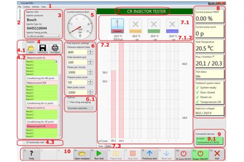
The main window is the “CR-Injector-Tester” mode tab

. The menu.
2. The mode selection tab “CR-Injector-Tester”.
In the “CR-Injector-Tester” mode tab are located:
3.The “Injector Info” (information about the injector).
4. “Testplan” (test plan).
4.1 Buttons for working with files and printing: “Open”, “Save”, “Print report”
4.2 The field for displaying the stages of the test plan (located under the buttons 4.1)
4.3 Check-box “Automatic test”.
5. The pressure gauge section “Current pressure (bar)”.
6.The section of parameters “Fuel Injection settings”.
6.1 The “Pressure setpoint (bar)” field is the injection pressure
7. Tab “Tester” – display of virtual flasks and parameters.
8. Visual display panels.
9.The “Connected Devices” unit showing the connection of devices.
10.Functional buttons of the software “CASCADE” – F1 … F12.
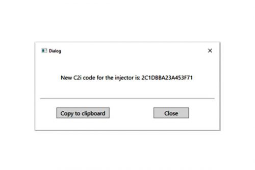
It is possible to set the encoding for an additional order.
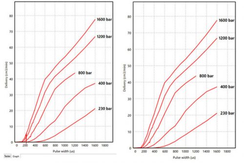
To encode the injectors, you need to get the test results. To do this, you need to select from the list of test plans by the number of the DELPHI injector. Open in the “Code with user target” or “Code with factory target” mode. After the end of the test plan, you can see the schedule and, if necessary, improve the results.


If the test plan is not available, use any new injector from the same “family” group, and use the “Make user target”


